
Introduction
About a month ago, while trying to figure out why a particular EDI Purchase Order system was not working properly, I got a vision about a scene for my video game that involves motorcycles driving by a lake. I know, it sounds like a delusion from alcohol poisoning, but the scene was very vivid and I really wanted to implement it. I pondered the pros and cons and after a while I concluded that it was already late September, thus there was no way to accomplish this scene and finish the game on time before the end of the year.
Weeks passed by, the scene kept popping on in my mind over and over (the EDI system kept failing too)… and then I decided to reconsider. Once again, I pondered the pros and cons and at the end I changed my mind and went for it. After all, we all do this for fun and, if I’m not happy with what I’m delivering, then there is no point in doing it anyway.
A Software Developer would have gone to an asset store and buy the 3D model that would fit best. However, a Graphic Designer would never let escape the opportunity of modeling such a stylish vehicle. I mean, if we were talking about a dirt bike then anything sturdy would do. But the game makes reference to some astrophysics concepts so I need something futuristic.
So I went ahead, undusted my drawing pad and started to indulge this nagging impulse I got that I knew it could very well cost me the project.
Besides, The last two development log entries were very technical (there is a gambling pool about the percentage of readers that will actually read the entire last article), so I thought it would be a good time to “flip hats”, cross to the artistic side of game development and share with other indies what works for me when it comes to create a 3D model. It may not be for everyone, but it works so well for me that this technique deserves the benefit of the doubt.
Step 1: Research
The very first step that any modeler should do is to research about the topic. Even if we were already experts, doing research will activate the right side of the brain and inspire our creative skills. Due to copyright laws, I cannot paste pictures on this article (well, I could for editorial purposes, but I don’t want to push my luck). It will suffice to say that browsing the Internet is a great (and cheap) way to learn about the topic at hand and get an idea about what the 3D model should look like.
Besides, I know absolutely nothing about motorcycles.
Step 2: Orthographic Drawing
When I was a young lad, I took a course about Technical Drawing and Industrial Design. Back then, I didn’t fully appreciate how useful the learned techniques were. Today, I know that this step is paramount for 3D modeling. Ok, granted, if you are modeling a character that looks like a sponge then by all means grab a cube, stretch it, add some eyes on it and you are all done. However, if you are creating something as stylish as a racing motorcycle then the orthographic drawing should be the first step to take.
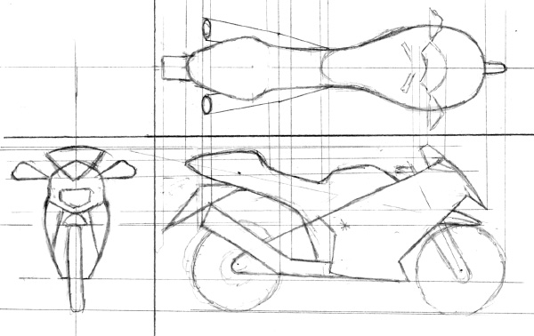
Ok, this drawing is awful. It is, by far, one of the most inaccurate orthographic drawings I have ever done, to the point that my technical drawing teacher would fail me in an instant. However, I’m on a hurry, and this drawing has all the information I need to start.
Step 3: Dissection
The first information that pops out from an orthographic drawing is the number of individual mesh parts that will be needed. Ok, granted, I could approach this as one big chaotic piece of clay. However, modeling is much easier if the object is divided in mesh parts and addressed them one at a time, even if at the end we may merge them in one big, not-so-chaotic-anymore, piece of clay.
The list of mesh parts came out as follows:
- Main Body
- Shield
- Front Wheel (including steering handle)
- Back Wheel
- Side Mirrors
- Tail Lights
- Escape Muffler
Step 4: Digitalization
Actually, the next step should have been to create an orthographic drawing for each and every mesh part identified in the previous step, but let’s face it, no one has the time to go through it, and it would be an overkill feat if we consider than all I need is a low polygon count 3D model.
So, instead of wasting time, I jumped to the step where I scan the orthographic drawing, ditch the pencil and paper and proceed with the digitalization process.
1. The first thing to identify is the center of mass. This is, by far, the most important coordinate. All axes will start from this coordinate. To identify the center of mass, what I do is to answer the following question: if the ground were to blow up, how would this model fly away, assuming no dismemberment would happen? As the object flies to its doom, the center of rotation would be the center of mass.
As Albert Einstein himself would say: “This is a thought experiment”. Do NOT do this at home. Or the office.
In case of my motorcycle, the center of mass is identified as the big bright green dot right in the middle (see next figure).
2. The next thing to do is to identify all axes. Usually, it’s one axis per mesh part. Since this is a man-made machine, this task is pretty easy. This task is also very important since some of this axes will become a “bone” in the 3D model’s skeleton (call it a “skin weight”).
3. The next step is to convert each mesh part into key vertices, assuming that a straight line between them will reproduce the original image. Think of it as the math version of drawing by numbers.
The orthographic drawing is very useful to identify key vertices, and I do this by putting a colored dot on all of them. Pretty much there must be at least one on every curve. The more vertices, the smother the curve will be. The projection lines are also an obvious indicator of where vertices are needed. Also, I add vertices in groups of four, assuming a transversal cut of the mesh part. This will be very useful later on.
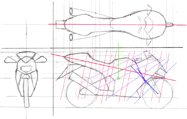
Now, each vertex must be identified in at least two views so I can measure the three coordinates needed to identify a vertex in space. In my case, I used the lateral and the top view. The front view was rather useless because a motorcycle is a rather complex object when seen from the front.
4. The last step of the digitalization process is to measure the distance from the mesh part’s vertices to the mesh part’s axis. Most graphic software have a tool to perform this measurement, although for simple models the pixel position minus the axis coordinate will suffice.
Step 4: Data Analysis and Vertex Extrapolation
Orthographic drawings are really useful for the modeling process. However, they can only give vertex information for at most six views. In order to create a 3D model that can be rotated at will, additional projections at different angles will be needed. The more projections, the smoother the 3D model will be. There are drawing techniques using fancy rulers that can be used to create the required orthographic projections on paper, but let’s face it, no one has that amount of time.
This is where software tools of the likes of “AutoCad” come to play: From the key vertices that were digitalized during the previous step, I extrapolate the information and estimate the location of vertices of different projections (hence the name “Key Vertices”).
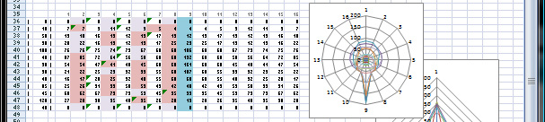
However, I have no budget for these software tools. No matter, though, for a similar analysis can be done using Microsoft’s Excel, assuming cylindrical coordinates.
Here is the plotted collected data for the main body mesh part (note the blunt sectional cuts on the right).
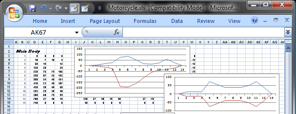
Here is the first iteration: Projection at 45 degrees.
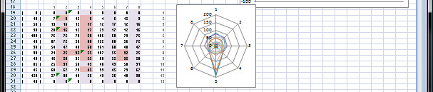
Here is the second iteration: Projection at 22.5 and 67.5 degrees.
I could continue, but these two iterations are more than enough for a low polygonal count 3D model.
Likewise, I did the same for the Shield and the Side Mirrors.
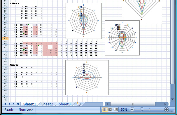
All other mesh parts are blunt cylinders so there was no need to get lost in calculations.
Step 5: Model Baking
Once all vertices have been identified, they can be put together in order to create the “faces” that will become the polygons of the 3D model.
I have a confession to make: I really, really wanted to use Paint3D for this project (Microsoft Contest = Microsoft Tools = Microsoft Technology). However, I couldn’t find a way to enter per-vertex information in this application. No matter, though, for there are plenty of other tools that can accept per-vertex information and bake them in a 3D model. The important knowledge here is how to create a model from a drawing all the way to the vertex buffer. In my very own particular case, I created a tool back in the good ol’ XNA days that will take per-vertex information from Excel and convert it to a 3D Model in an X-File. If I didn’t have this tool, I’d dump the information using Notepad in an OBJ file (although this file format does not support skin weights).
Step 6: Painting
Once all vertices have been baked, the end result is a monochromatic model on the screen. Depending on the software used for baking, a texture can be associated, which implies the calculation of texture coordinate for every vertex. In my case, I rather skip the texture and focus instead on a material color approach. Later, at run-time, I can change the texture at will so I can have the same model in different colors / ensembles. The final result can be seen in the video attached to this page.
Conclusion
The process that I follow for 3D modeling may seem a little convoluted for many fellow indie game developers. However, the important knowledge are not the choice of software tools, but the process of how to create a 3D model starting from the drawing board (literally) all the way to the data collection phase. If I were to use Maya, Blender, Colada or Paint3D, I would always start with the research and the orthographic drawing anyway. This process gives me a very tight control of the position of each vertex that translates to an accurate 3D model of the drawing at hand. As you can see in the images and the attached video, it really works for me. This motorcycle took me six days of my precious free time (about 15 hours in total – damn hockey games)… and I enjoyed every minute of it.
